InterSystems Technologies on Amazon EC2: Reference Architecture
Enterprises need to grow and manage their global computing infrastructures rapidly and efficiently while simultaneously optimizing and managing capital costs and expenses. Amazon Web Services (AWS) and Elastic Compute Cloud (EC2) computing and storage services meet the needs of the most demanding Caché based application by providing a highly robust global computing infrastructure.
The Amazon EC2 infrastructure enables companies to rapidly provision compute capacity and/or quickly and flexibly extend their existing on- premises infrastructure into the cloud. AWS provides a rich set of services and robust, enterprise-grade mechanisms for security, networking, computation, and storage.
At the heart of AWS is the Amazon EC2. A cloud computing infrastructure that supports a variety of operating systems and machine configurations (e.g., CPU, RAM, network). AWS provides preconfigured virtual machine (VM) images known as Amazon Machine Images, or AMIs, with guest operating systems including various Linux® and Windows distributions and versions. They may have additional software used as the basis for virtualized instances running in AWS. You can use these AMIs as starting points to instantiate and install or configure additional software, data, and more to create application- or workload-specific AMIs.
Care must be taken, as with any platform or deployment model, to ensure all aspects of an application environment are considered such as performance, availability, operations, and management procedures.
Specifics of each of following areas will be covered in this document.
- Network setup and configuration. This section covers the setup of the network for Caché-based applications within AWS, including subnets to support the logical server groups for different layers and roles within the reference architecture.
- Server setup and configuration. This section covers the services and resources involved in the design of the various servers for each layer. It also includes the architecture for high availability across availability zones.
- Security. This section discusses security mechanisms in AWS, including how to configure the instance and network security to enable authorized access to the overall solution as well as between layers and instances.
- Deployment and management. This section provides details on packaging, deployment, monitoring, and management.
Architecture and Deployment Scenarios
This document provides several reference architectures within AWS as examples for providing robust well performing and highly available applications based on InterSystems technologies including Caché, Ensemble, HealthShare, TrakCare, and associated embedded technologies such as DeepSee, iKnow, CSP, Zen and Zen Mojo.
To understand how Caché and associated components can be hosted on AWS, let’s first review the architecture and components of a typical Caché deployment and explore some common scenarios and topologies.
Caché Architecture Review
InterSystems data platform continuously evolves to provide an advanced database management system and rapid application development environment for breakthroughs in processing and analyzing complex data models and developing Web and mobile applications.
This is a new generation of database technology that provides multiple modes of data access. Data is only described once in a single integrated data dictionary and is instantly available using object access, high-performance SQL, and powerful multidimensional access – all of which can simultaneously access the same data.
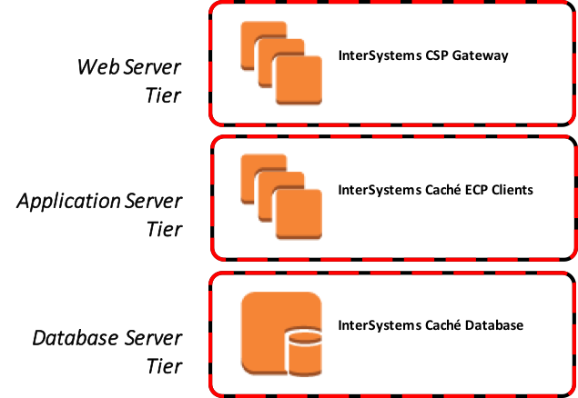
The available Caché high-level architecture component tiers and services are illustrated in Figure-1. These general tiers also apply to both InterSystems TrakCare and HealthShare products as well.
Figure-1: High-level component tiers
Common Deployment Scenarios
There are numerous combinations possible for deployment, however in this document two scenarios will be covered; a hybrid model and complete cloud hosted model.
Hybrid Model
In this scenario, a company wants to leverage both on-premises enterprise resources and AWS EC2 resources for either disaster recovery, internal maintenance contingency, re-platforming initiatives, or short/long term capacity augmentation when needed. This model can offer a high level of availability for business continuity and disaster recovery for a failover mirror member set on-premises.
Connectivity for this model in this scenario relies on a VPN tunnel between the on-premises deployment and the AWS availability zone(s) to present AWS resources as an extension to the enterprise’s data center. There are other connectivity methods such as AWS Direct Connect. However, this is not covered as part of this document. Further details about AWS Direct Connect can be found here.
Details for setting up this example Amazon Virtual Private Cloud (VPC) to support disaster recovery of your on-premises data center can he found here.
Figure-2: Hybrid model using AWS VPC for disaster recovery of on-premises
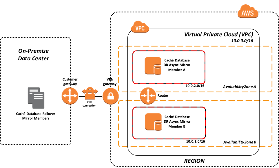
The above example shows a failover mirror pair operating within your on-premises data center with a VPN connection to your AWS VPC. The VPC illustrated provides multiple subnets in dual availability zones in a given AWS region. There are two Disaster Recovery (DR) Async mirror members (one in each availability zone) to provide resiliency.
Cloud Hosted Model
In this scenario, your Caché-based application including both data and presentation layers are kept completely in the AWS cloud using multiple availability zones within a single AWS region. The same VPN tunnel, AWS Direct Connect, and even pure Internet connectivity models are available.
Figure-3: Cloud hosted model supporting full production workload
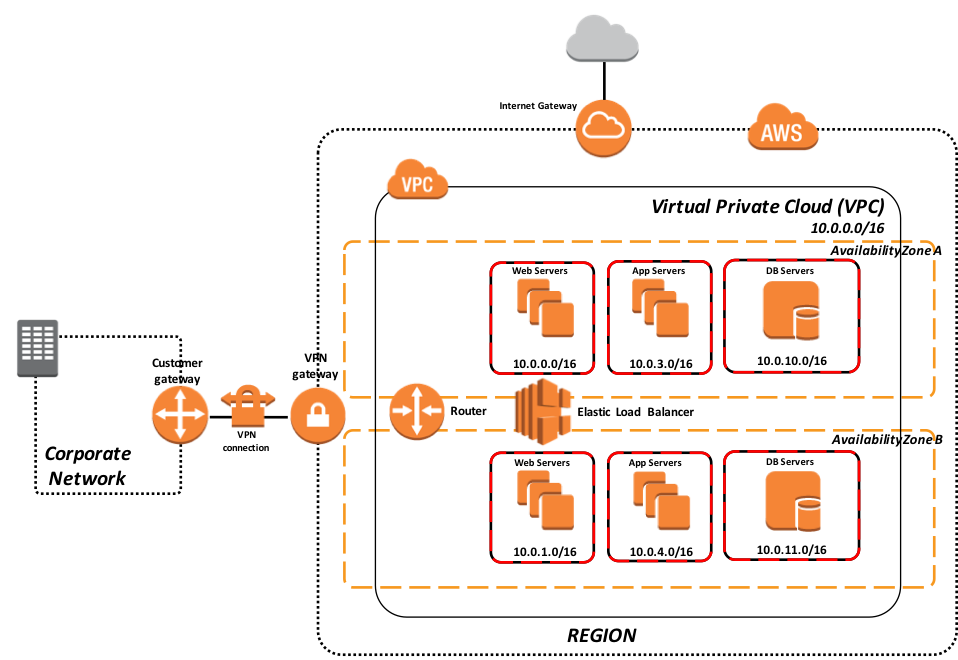
The above example in Figure-3 illustrates a deployment model for supporting an entire production deployment of your application in your VPC. This model leverages dual availability zones with synchronous failover mirroring between the availability zones along with load balanced web servers and associated application servers as ECP clients. Each tier is isolated in a separate security group for network security controls. IP addresses and port ranges are only opened as required based on your application’s needs.
Storage and Compute Resource
Storage
There are multiple types of storage options available. For the purpose of this reference architecture Amazon Elastic Block Store (Amazon EBS) and Amazon EC2 Instance Store (also called ephemeral drives) volumes are discussed for several possible use cases. Additional details of the various storage options can be found here and here.
Elastic Block Storage (EBS)
EBS provides durable block-level storage for use with Amazon EC2 instances (virtual machines) which can be formatted and mounted as traditional file systems in either Linux or Windows, and most importantly the volumes are off-instance storage that persists independently from the running life of a single Amazon EC2 instance which is important for database systems.
In addition, Amazon EBS provides the ability to create point-in-time snapshots of volumes, which are persisted in Amazon S3. These snapshots can be used as the starting point for new Amazon EBS volumes, and to protect data for long-term durability. The same snapshot can be used to instantiate as many volumes as you want. These snapshots can be copied across AWS regions, making it easier to leverage multiple AWS regions for geographical expansion, data center migration, and disaster recovery. Sizes for Amazon EBS volumes range from 1 GB to 16 TB, and are allocated in 1 GB increments.
Within Amazon EBS there are three different types: Magnetic Volumes, General Purpose (SSD), and Provisioned IOPS (SSD). The following sub sections provide a short description of each.
Magnetic Volumes
Magnetic volumes offer cost-effective storage for applications with moderate or bursting I/O requirements. Magnetic volumes are designed to deliver approximately 100 input/output operations per second (IOPS) on average, with a best effort ability to burst to hundreds of IOPS. Magnetic volumes are also well- suited for use as boot volumes, where the burst capability provides fast instance startup times.
General Purpose (SSD)
General Purpose (SSD) volumes offer cost-effective storage that is ideal for a broad range of workloads. These volumes deliver single-digit millisecond latencies, the ability to burst to 3,000 IOPS for extended periods of time, and a baseline performance of 3 IOPS/GB up to a maximum of 10,000 IOPS (at 3,334 GB). General Purpose (SSD) volumes can range in size from 1 GB to 16 TB.
Provisioned IOPS (SSD)
Provisioned IOPS (SSD) volumes are designed to deliver predictable high performance for I/O-intensive workloads, such as database workloads that are sensitive to storage performance and consistency in random access I/O throughput. You specify an IOPS rate when creating a volume, and then Amazon EBS delivers within 10 percent of the provisioned IOPS performance 99.9 percent of the time over a given year. A Provisioned IOPS (SSD) volume can range in size from 4 GB to 16 TB, and you can provision up to 20,000 IOPS per volume. The ratio of IOPS provisioned to the volume size requested can be a maximum of 30; for example, a volume with 3,000 IOPS must be at least 100 GB in size. Provisioned IOPS (SSD) volumes have a throughput limit range of 256 KB for each IOPS provisioned, up to a maximum of 320 MB/second (at 1,280 IOPS).
The architectures discussed in this document use EBS volumes as these are more suited for production workloads that require predictable low-latency Input/Output Operations per Second (IOPs) and throughput. Care must be taken when selecting a particular VM type because not all EC2 instance types can have access to EBS storage.
Details about EBS volumes can be found here.
EC2 Instance Storage (ephemeral drives)
EC2 instance storage consists of a preconfigured and pre-attached block of disk storage on the same physical server that hosts your operating Amazon EC2 instance. The amount of the disk storage provided varies by Amazon EC2 instance type. In the Amazon EC2 instance families that provide instance storage, larger instances tend to provide both more and larger instance store volumes.
There are storage-optimized (I2) and dense-storage (D2) Amazon EC2 instance families that provide special-purpose instance storage that are targeted to specific use cases. For example, I2 instances provide very fast SSD-backed instance storage capable of supporting over 365,000 random read IOPS and 315,000 write IOPS and provide cost attractive pricing models.
Unlike EBS volumes, the storage is not permanent and can be only used for the instance’s lifetime, and cannot be detached or attached to another instance. Instance storage is meant for temporary storage of information that is continually changing. In the realm of InterSystems technologies and products, items such as using Ensemble or Health Connect as an Enterprise Service Bus (ESB), application servers using Enterprise Cache Protocol (ECP), or using web servers with CSP Gateway would be great use cases for this type of storage and storage-optimized instance types along with using provisioning and automation tools to streamline their effectiveness and support elasticity.
Details about Instance store volumes can be found here.
Compute
EC2 Instances
There are numerous instance types available that are optimized for various use cases. Instance types comprise varying combinations of CPU, memory, storage, and networking capacities allowing for countless combinations to right-size the resource requirements for your application.
For the purpose of this document General Purpose M4 Amazon EC2 instance types will be referenced as means to right-size an environment and these instances provide EBS volume capabilities and optimizations. Alternatives are possible based on your application’s capacity requirements and pricing models.
M4 instances are the latest generation of General Purpose instances. This family provides a balance of compute, memory, and network resources, and it is a good choice for many applications. Capacities range from 2 to 64 virtual CPU and 8 to 256GB of memory with corresponding dedicated EBS bandwidth.
In addition to the individual instance types, there are also tiered classifications such as Dedicated Hosts, Spot instances, Reserved instances, and Dedicated instances each with varying degrees of pricing, performance, and isolation.
Confirm availability and details of the currently available instances here.
Availability and Operations
Web/App Server Load Balancing
External and internal load balanced web servers may be required for your Caché based application. External load balancers are used for access over the Internet or WAN (VPN or Direct Connect) and internal load balancers are potentially used for internal traffic. AWS Elastic Load balancing provides two types of load balancers – Application load balancer and Classic Load balancer.
Classic Load Balancer
The Classic Load Balancer routes traffic based on application or network level information and is ideal for simple load balancing of traffic across multiple EC2 instances where high availability, automatic scaling, and robust security are required. The specific details and features can be found here.
Application Load Balancer
An Application Load Balancer is a load balancing option for the Elastic Load Balancing service that operates at the application layer and allows you to define routing rules based on content across multiple services or containers running on one or more Amazon EC2 instances. Additionally, there is support for WebSockets and HTTP/2. The specific details and features can be found here.
Example
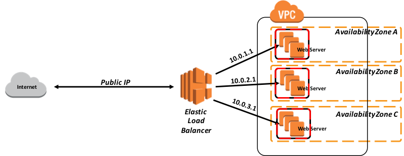
In this following example, a set of three web servers are defined with each one in a separate availability zone to provide the highest levels of availability. The web server load balancers must be configured with Sticky Sessions to support the ability to pin user sessions to specific EC2 instances using cookies. Traffic will be routed to the same instances as the user continues to access your application.
The following diagram in Figure-4 illustrates a simple example of the Classic Load Balancer within AWS.
Figure-4: Example of a Classic Load Balancer
Database Mirroring
When deploying Caché based applications on AWS, providing high availability for the Caché database server requires the use of synchronous database mirroring to provide high availability in a given primary AWS region and potentially asynchronous database mirroring to replicate data to a hot standby in a secondary AWS region for disaster recovery depending on your uptime service level agreements requirements.
A database mirror is a logical grouping of two database systems, known as failover members, which are physically independent systems connected only by a network. After arbitrating between the two systems, the mirror automatically designates one of them as the primary system; the other member automatically becomes the backup system. External client workstations or other computers connect to the mirror through the mirror Virtual IP (VIP), which is specified during mirroring configuration. The mirror VIP is automatically bound to an interface on the primary system of the mirror.
The current recommendation for deploying a database mirror in AWS is to configure three instances (primary, backup, arbiter) in the same VPC across three different availability zones. This ensures that at any given time, AWS will guarantee external connectivity with at least two of these VMs with a 99.95% SLA. This provides adequate isolation and redundancy of the database data itself. Details on AWS EC2 service level agreements can be found here.
There is no hard upper limit on network latency between failover members. The impact of increasing latency differs by application. If the round trip time between the failover members is similar to the disk write service time, no impact is expected. Round trip time may be a concern, however, when the application must wait for data to become durable (sometimes referred to as a journal sync). Details of database mirroring and network latency can be found here.
Virtual IP Address and Automatic Failover
Most IaaS cloud providers lack the ability to provide for a Virtual IP (VIP) address that is typically used in database failover designs. To address this, several of the most commonly used connectivity methods, specifically ECP clients and CSP Gateways, have been enhanced within Caché, Ensemble, and HealthShare to no longer rely on VIP capabilities making them mirror-aware.
Connectivity methods such as xDBC, direct TCP/IP sockets, or other direct connect protocols, still require the use of a VIP. To address those, InterSystems database mirroring technology makes it possible to provide automatic failover for those connectivity methods within AWS using APIs to interact with either an AWS Elastic Load Balancer (ELB) to achieve VIP-like functionality, thus providing a complete and robust high availability design within AWS.
Additionally, AWS has recently introduced a new type of ELB called an Application Load Balancer. This type of load balancer runs at Layer 7 and supports content-based routing and supports applications that run in containers. Content based routing is especially useful for Big Data type projects using a partitioned data or data sharding deployment.
Just as with Virtual IP, this is an abrupt change in network configuration and does not involve any application logic to inform existing clients connected to the failed primary mirror member that a failover is happening. Depending on the nature of the failure, those connections can get terminated as a result of the failure itself, due to application timeout or error, as a result of the new primary forcing the old primary instance down, or due to expiration of the TCP keep-alive timer used by the client.
As a result, users may have to reconnect and log in. Your application’s behavior would determine this behavior. Details about the various types of available ELB can be found here.
AWS EC2 Instance call-out to AWS Elastic Load Balancer Method
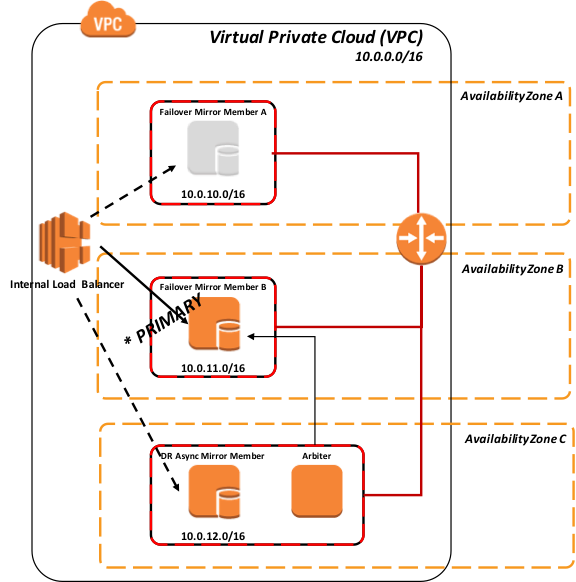
In this model the ELB can either have a server pool defined with both failover mirror members and potentially DR asynchronous mirror member(s) with only one of the entries active that is the current primary mirror member, or only a server pool with single entry of the active mirror member.
Figure-5: API Method to interact with Elastic Load Balancer (internal)
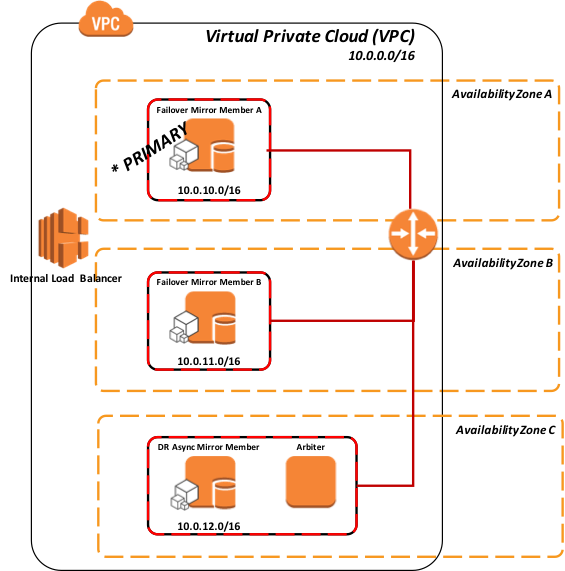
When a mirror member becomes the primary mirror member an API call is issued from your EC2 instance to the AWS ELB to adjust/instruct the ELB of the new primary mirror member.
Figure-6: Failover to Mirror Member B using API to Load Balancer
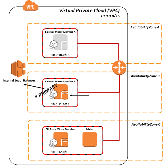
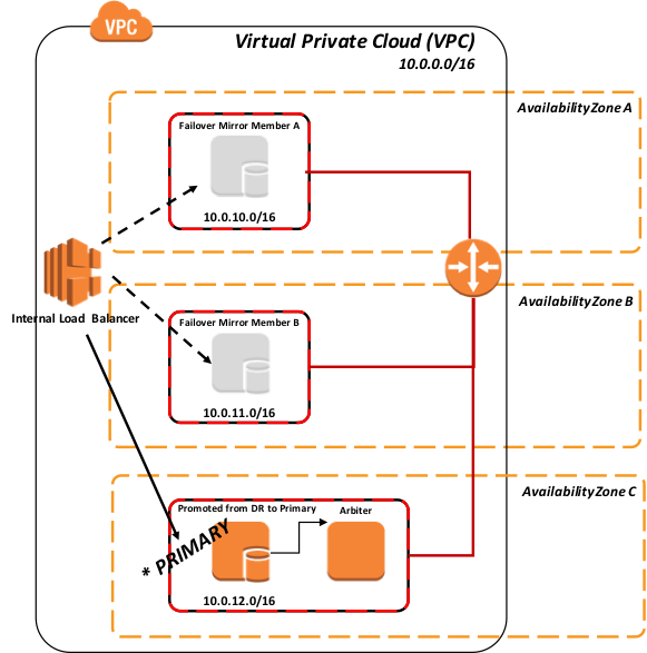
The same model applies for promoting a DR Asynchronous mirror member in the event of both the primary and backup mirror members become unavailable.
Figure-7: Promotion of DR Async mirror to primary using API to Load Balancer
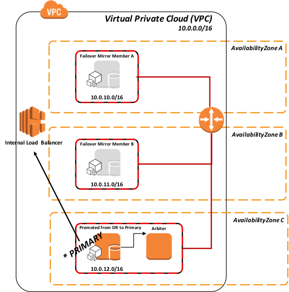
As per standard recommended DR procedure, in Figure-6 above the promotion of the DR member involves a human decision due to the possibility of data loss from asynchronous replication. Once that action is taken however, no administrative action is required on the ELB. It automatically routes traffic once the API is called during promotion.
API Details
This API to call-out to the AWS load balancer resource is defined in the ^ZMIRROR routine specifically as part of the procedure call:
$$CheckBecomePrimaryOK^ZMIRROR()
Within this procedure, insert whatever API logic or methods you chose to use from AWS ELB REST API, command line interface, etc. An effective and secure way to interact with the ELB is to use AWS Identity and Access Management (IAM) roles so you don’t have to distribute long-term credentials to an EC2 instance. The IAM role supplies temporary permissions that Caché can use to interact with the AWS ELB. Details for using IAM roles assigned to your EC2 instances can be found here.
AWS Elastic Load Balancer Polling Method
A polling method using the CSP Gateway’s mirror_status.cxw page available in 2017.1 can be used as the polling method in the ELB health monitor to each mirror member added to the ELB server pool. Only the primary mirror will respond ‘SUCCESS’ thus directing network traffic to only the active primary mirror member.
This method does not require any logic to be added to ^ZMIRROR. Please note that most load-balancing network appliances have a limit on the frequency of running the status check. Typically, the highest frequency is no less than 5 seconds, which is usually acceptable to support most uptime service level agreements.
A HTTP request for the following resource will test the Mirror Member status of the LOCAL Cache configuration.
/csp/bin/mirror_status.cxw
For all other cases, the path to these Mirror status requests should resolve to the appropriate Cache server and NameSpace using the same hierarchical mechanism as that used for requesting real CSP pages.
Example: To test the Mirror Status of the configuration serving applications in the /csp/user/ path:
/csp/user/mirror_status.cxw
Depending on whether or not the target instance is the active Primary Member the Gateway will return one of the following CSP responses:
** Success (Is the Primary Member)
===============================
HTTP/1.1 200 OK
Content-Type: text/plain
Connection: close
Content-Length: 7
SUCCESS
** Failure (Is not the Primary Member)
===============================
HTTP/1.1 503 Service Unavailable
Content-Type: text/plain
Connection: close
Content-Length: 6
FAILED
** Failure (The Cache Server does not support the Mirror_Status.cxw request)
===============================
HTTP/1.1 500 Internal Server Error
Content-Type: text/plain
Connection: close
Content-Length: 6
FAILED
The following figures illustrate the various scenarios of using the polling method.
Figure-8: Polling to all mirror members
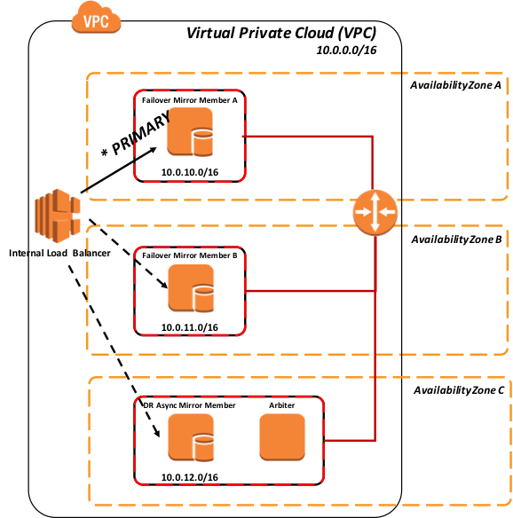
As the above Figure-8 shows, all mirror members are operational, and only the primary mirror member is returning “SUCCESS” to the load balancer, and so network traffic will be directed to only this mirror member.
Figure-9: Failover to Mirror Member B using polling
The following diagram demonstrates the promotion of DR asynchronous mirror member(s) into the load-balanced pool, this typically assumes the same load-balancing network appliance is servicing all mirror members (geographically split scenarios are covered later in this article).
As per standard recommended DR procedure, the promotion of the DR member involves a human decision due to the possibility of data loss from asynchronous replication. Once that action is taken however, no administrative action is required on the ELB. It automatically discovers the new primary.
Figure-10: Failover and Promotion of DR Asynchronous Mirror Member using polling
Backup and Restore
There are multiple options available for backup operations. The following three options are viable for your AWS deployment with InterSystems products. The first two options incorporate a snapshot type procedure which involves suspending database writes to disk prior to creation of the snapshot and then resuming updates once the snapshot was successful. The following high-level steps are taken to create a clean backup using either of the snapshot methods:
- Pause writes to the database via database Freeze API call.
- Create snapshots of the operating system + data disks.
- Resume Caché writes via database Thaw API call.
- Backup facility archives to backup location
Additional steps such as integrity checks can be added on a periodic interval to ensure a clean and consistent backup.
The decision points on which option to use depends on the operational requirements and policies of your organization. InterSystems is available to discuss the various options in more detail.
EBS Snapshots
EBS snapshots are very fast and efficient ways to create a point-in-time snapshot onto highly available and lower cost Amazon S3 storage. EBS snapshots along with InterSystems External Freeze and Thaw API capabilities allow for true 24x7 operational resiliency and assurance of clean regular backups. There are numerous options for automating the process using both AWS provided services such as Amazon CloudWatch Events or 3rd party solutions available in the marketplace such as Cloud Ranger or N2W Software Cloud Protection Manager to name a few.
Additionally, you can programmatically create your own customized backup solution via the use of AWS direct API calls. Details on how to leverage the APIs are available here and here.
Logical Volume Manager Snapshots
Alternatively, many of the third-party backup tools available on the market can be used by deploying individual backup agents within the VM itself and leveraging file-level backups in conjunction with Linux Logical Volume Manager (LVM) snapshots or Windows Volume Shadow Copy Service (VSS).
One of the major benefits to this model is having the ability to have file-level restores of Linux and Windows based instances. A couple of points to note with this solution; since AWS and most other IaaS cloud providers do not provide tape media, all backup repositories are disk-based for short term archiving and have the ability to leverage Amazon S3 low cost storage and eventually Amazon Glacier for long-term retention (LTR). It is highly recommended if using this method to use a backup product that supports de-duplication technologies to make the most efficient use of disk-based backup repositories.
Some examples of these backup products with cloud support include but is not limited to: Commvault, EMC Networker, HPE Data Protector, and Veritas Netbackup.
Caché Online Backup
For small deployments the built-in Caché Online Backup facility is also a viable option. The InterSystems database online backup utility backs up data in database files by capturing all blocks in the databases then writes the output to a sequential file. This proprietary backup mechanism is designed to cause no downtime to users of the production system.
In AWS, after the online backup has finished, the backup output file and all other files in use by the system must be copied to an EC2 acting as a file share (CIFS/NFS). This process needs to be scripted and executed within the virtual machine.
Online backup is the entry-level approach for smaller sites wishing to implement a low cost solution for backup. However, as databases increase in size, external backups with snapshot technology are recommended as a best practice with advantages including the backup of external files, faster restore times, and an enterprise-wide view of data and management tools.
Disaster Recovery
When deploying a Caché based application on AWS, DR resources including network, servers and storage are recommended to be in a different AWS region or at a minimum separate availability zones. The amount of capacity required in the designated DR AWS region depends on your organizational needs. In most cases 100% of the production capacity is required when operating in a DR mode, however lesser capacity can be provisioned until more is needed as an elastic model. Lesser capacity can be in the form of fewer web and application servers and potentially even a smaller EC2 instance type for the database server can be used and upon promotion the EBS volumes are attached to a large EC2 instance type.
Asynchronous database mirroring is used to continuously replicate to the DR AWS region’s EC2 instances. Mirroring uses database transaction journals to replicate updates over a TCP/IP network in a way that has minimal performance impact on the primary system. Journal file compression and encryption is highly recommended to be configured with these DR Asynchronous mirror members.
All external clients on the public Internet who wish to access the application will be routed through Amazon Route53 as an added DNS service. Amazon Route53 is used as a switch to direct traffic to the current active data center. Amazon Route53 performs three main functions:
- Domain registration – Amazon Route53 lets you register domain names such as example.com.
- Domain Name System (DNS) service – Amazon Route53 translates friendly domains names like www.example.com into IP addresses like 192.0.2.1. Amazon Route53 responds to DNS queries using a global network of authoritative DNS servers, which reduces latency.
- Health checking – Amazon Route53 sends automated requests over the Internet to your application to verify that it's reachable, available, and functional.
Details of these functions can be found here.
For the purpose of this document DNS Failover and Route53 Health Checking will be discussed. Details of Health Check monitoring and DNS failover can be found here and here.
Route53 works by making regular requests to each endpoint and then verifying the response. If an endpoint fails to provide a valid response. It is no longer included in DNS responses, which instead will return an alternative, available endpoint. In this way, user traffic is directed away from failing endpoints and toward endpoints that are available.
Using the above methods traffic will only be allowed to a specific region and specific mirror member. This is controlled by the endpoint definition which is a mirror_status.cxw page discussed previously in this article presented from the InterSystems CSP Gateway. Only the primary mirror member will ever report “SUCCESS” as a HTTP 200 from the health check.
The following diagram demonstrates at a high-level the Failover Routing Policy. Details of this method and others can be found here.
Figure-11: Amazon Route53 Failover Routine Policy

At any given time, only one of the regions will report online based on the endpoint monitoring. This ensures that traffic only flows to one region at a given time. There are no added steps needed for failover between the regions since the endpoint monitoring will detect the application in the designated primary AWS region is down and the application is now live in the secondary AWS region. This is because the DR Asynchronous mirror member has been manually promoted to primary which then allows the CSP Gateway to report HTTP 200 to the Elastic Load Balancer endpoint monitoring.
There are many alternatives to the above described solution, and can be customized based on your organization operational requirements and service level agreements.
Monitoring
Amazon CloudWatch is available to provide monitoring services for all your AWS cloud resources and your applications. Amazon CloudWatch can be used to collect and track metrics, collect and monitor log files, set alarms, and automatically react to changes in AWS resources. Amazon CloudWatch can monitor AWS resources such as Amazon EC2
instances as well as custom metrics generated by your applications and services, and any log files your applications generate. You can use Amazon CloudWatch to gain system-wide visibility into resource utilization, application performance, and operational health. Details can be found here.
Automated Provisioning
There are numerous tools available on the market today including Terraform, Cloud Forms, Open Stack, and Amazon’s own CloudFormation. Using these and coupling with other tools such as Chef, Puppet, Ansible, and others can provide for the complete Infrastructure-as-Code supporting DevOps or simply bootstrapping your application in a completely automated fashion. Details of Amazon CloudFormation can be found here.
Network Connectivity
Depending on your application’s connectivity requirements, there are multiple connectivity models available using either Internet, VPN, or a dedicated link using Amazon Direct Connect. The method to choose will depend on the application and user needs. The bandwidth usage for each of the three methods vary, and best to check with your AWS representative or Amazon Management Console for confirmation of available connectivity options for a given region.
Security
Care needs to be taken when deciding to deploy an application in any public IaaS cloud provider. Your organization’s standard security policies, or new ones developed specifically for cloud, should be followed to maintain security compliance of your organization. You will also have to understand data sovereignty which is relevant when an organization’s data is stored outside of their country and is subject to the laws of the country in which the data resides. Cloud deployments have the added risk of data now outside client data centers and physical security control. The use of InterSystems database and journal encryption for data at rest (databases and journals) and data in flight (network communications) with AES and SSL/TLS encryption respectively are highly recommended.
As with all encryption key management, proper procedures need to be documented and followed per your organization’s policies to ensure data safety and prevent unwanted data access or security breech.
Amazon provides extensive documentation and examples to provide for a highly secure operating environment for your Caché based applications. Be sure to review the Identity Access Management (IAM) for various discussion topics found here.
Architecture Diagram Examples
The diagram below illustrates a typical Caché installation providing high availability in the form of database mirroring (both synchronous failover and DR Asynchronous), application servers using ECP, and multiple load balanced web servers.
TrakCare Example
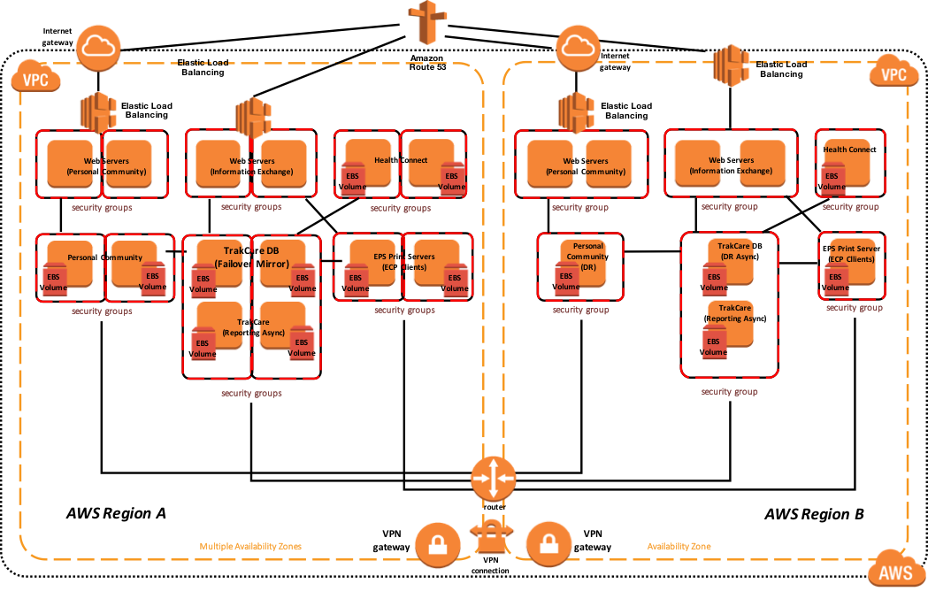
The following diagram illustrates a typical TrakCare deployment with multiple load balanced webservers, two print servers as ECP clients, and database mirror configuration. The Virtual IP address is only used for connectivity not associated with ECP or the CSP Gateway. The ECP clients and CSP Gateway are mirror-aware and do not require a VIP.
If you are using Direct Connect, there are several options including multiple circuits and multi-region access that can be enabled for disaster recovery scenarios. It is important to work with the telecommunications provider(s) to understand the high availability and disaster recovery scenarios they support.
The sample reference architecture diagram below includes high availability in the active or primary region, and disaster recovery to another AWS region if the primary AWS region is unavailable. Also within this example, the database mirrors contain the TrakCare DB, TrakCare Analytics, and Integration namespace all within that single mirror set.
Figure-12: TrakCare AWS Reference Architecture Diagram – Physical Architecture
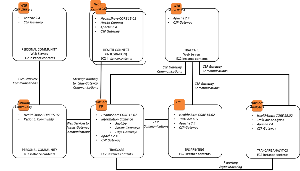
 In addition, the following diagram is provided showing a more logical view of architecture with the associated high-level software products installed and functional purpose.
Figure-13: TrakCare AWS Reference Architecture Diagram – Logical Architecture
HealthShare Example
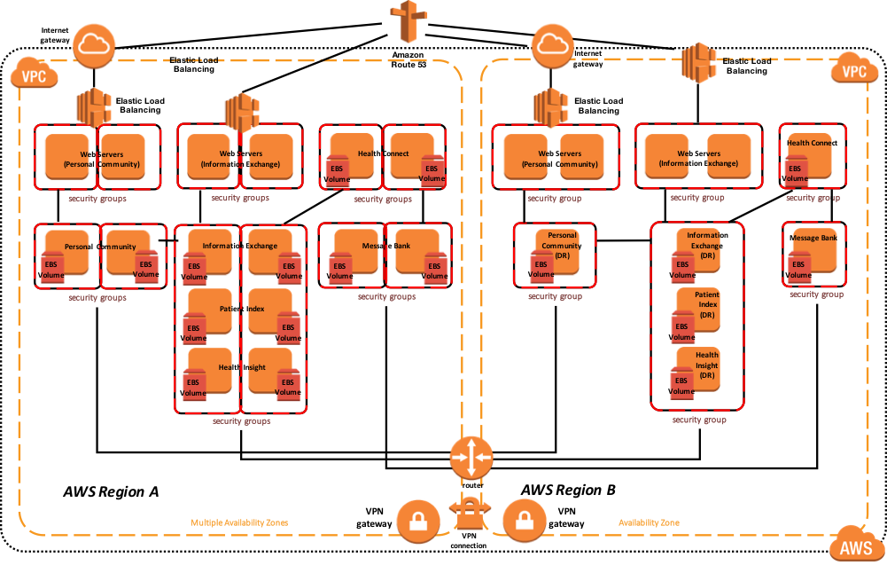
The following diagram illustrates a typical HealthShare deployment with multiple load balanced webservers, with multiple HealthShare products including Information Exchange, Patient Index, Personal Community, Health Insight, and Health Connect. Each of those respective products include a database mirror pair for high availability within multiple availability zones. The Virtual IP address is only used for connectivity not associated with ECP or the CSP Gateway. The CSP Gateways used for web service communications between the HealthShare products are mirror-aware and do not require a VIP.
The sample reference architecture diagram below includes high availability in the active or primary region, and disaster recovery to another AWS region if the primary region is unavailable.
Figure-14: HealthShare AWS Reference Architecture Diagram – Physical Architecture
In addition, the following diagram is provided showing a more logical view of architecture with the associated high-level software products installed, connectivity requirements and methods, and the respective functional purpose.
Figure-15: HealthShare AWS Reference Architecture Diagram – Logical Architecture