Database Mirroring without a Virtual IP Address
++ Update: August 1, 2018
The use of the InterSystems Virtual IP (VIP) address built-in to Caché database mirroring has certain limitations. In particular, it can only be used when mirror members reside the same network subnet. When multiple data centers are used, network subnets are not often “stretched” beyond the physical data center due to added network complexity (more detailed discussion here). For similar reasons, Virtual IP is often not usable when the database is hosted in the cloud.
Network traffic management appliances such as load balancers (physical or virtual) can be used to achieve the same level of transparency, presenting a single address to the client applications or devices. The network traffic manager automatically redirects clients to the current mirror primary’s real IP address. The automation is intended to meet the needs of both HA failover and DR promotion following a disaster.
Integration of a Network Traffic Manager
There are numerous options on the market today that support network traffic redirection. Each of these supports similar and even multiple methodologies for controlling network flow based on the application requirements. To simplify these methodologies, we consider three categories: Database Server Invoked API, Network Appliance Polling, or a combination of both.
The following section will outline each of these methodologies and provide guidance on how each of these can be integrated with InterSystems products. In all scenarios the arbiter is used to provide safe failover decisions when the mirror members cannot directly communicate. Details on the arbiter can be found here.
For the purposes of this article, the example diagrams will depict 3 mirror members: primary, backup, and DR Async. However, we recognize your configuration may have greater or fewer than this.
Option 1: Network Appliance Polling (Recommended)
In this method, the network load-balancing appliance uses its built in polling mechanism to communicate with both mirror members to determine the primary mirror member.
A polling method using the CSP Gateway’s mirror_status.cxw page available in 2017.1 can be used as the polling method in the ELB health monitor to each mirror member added to the ELB server pool. Only the primary mirror will respond ‘SUCCESS’ thus directing network traffic to only the active primary mirror member.
This method does not require any logic to be added to ^ZMIRROR. Please note that most load-balancing network appliances have a limit on the frequency of running the status check. Typically, the highest frequency is no less than 5 seconds, which is usually acceptable to support most uptime service level agreements.
A HTTP request for the following resource will test the Mirror Member status of the LOCAL Cache configuration.
/csp/bin/mirror_status.cxw
For all other cases, the path to these Mirror status requests should resolve to the appropriate Cache server and NameSpace using the same hierarchical mechanism as that used for requesting real CSP pages.
Example: To test the Mirror Status of the configuration serving applications in the /csp/user/ path:
/csp/user/mirror_status.cxw
Note: A CSP license is not consumed by invoking a Mirror Status check.
Depending on whether or not the target instance is the active Primary Member the Gateway will return one of the following CSP responses:
** Success (Is the Primary Member)
===============================
HTTP/1.1 200 OK
Content-Type: text/plain
Connection: close
Content-Length: 7
SUCCESS
** Failure (Is not the Primary Member)
===============================
HTTP/1.1 503 Service Unavailable
Content-Type: text/plain
Connection: close
Content-Length: 6
FAILED
** Failure (The Cache Server does not support the Mirror_Status.cxw request)
===============================
HTTP/1.1 500 Internal Server Error
Content-Type: text/plain
Connection: close
Content-Length: 6
FAILED
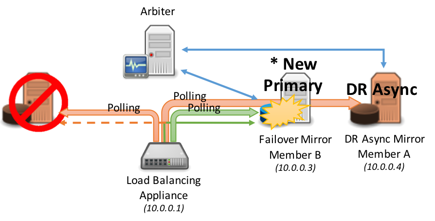
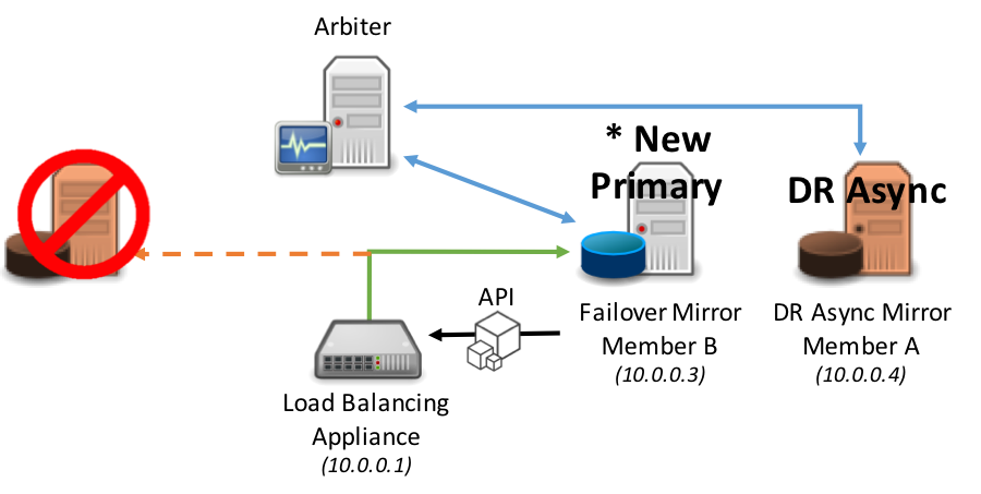
Consider the following diagrams as an example of polling.
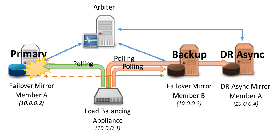
Failover occurs automatically between the synchronous failover mirror members:
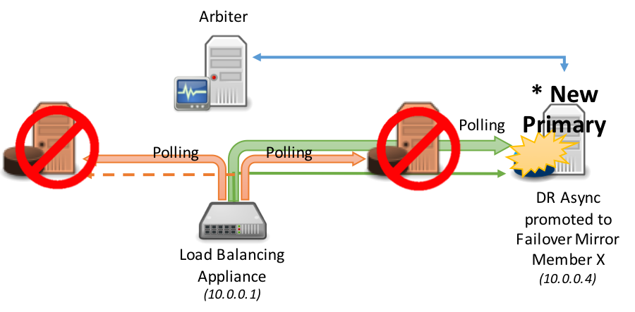
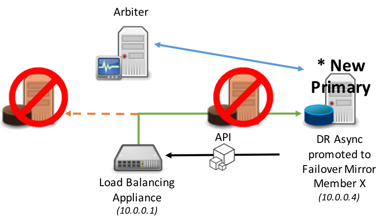
The following diagram demonstrates the promotion of DR asynchronous mirror member(s) into the load-balanced pool, this typically assumes the same load-balancing network appliance is servicing all mirror members (geographically split scenarios are covered later in this article). As per standard DR procedure the promotion of the disaster recovery member involves a human decision and then a simple administrative action at the database level. Once that action is taken however, no administrative action is required on the network appliance: it automatically discovers the new primary.
Option 2: Database Server Invoked API
In this method the network traffic management appliance is used and has a server pool defined with both failover mirror members and potentially DR asynchronous mirror member(s).
When a mirror member becomes the primary mirror member an API call is issued to the network appliance to adjust the priority or weighting to immediately instruct the network appliance to direct network traffic to the new primary mirror member.
The same model applies to promotion of a DR Async mirror member in the event of both the primary and backup mirror members become unavailable.
This API is defined in the ^ZMIRROR routine specifically as part of the procedure call: $$CheckBecomePrimaryOK^ZMIRROR()
Within this procedure call, insert whatever API logic and methods available for the corresponding network appliance such as REST API, command line interface, etc. Just as with Virtual IP, this is an abrupt change in network configuration and does not involve any application logic to inform existing clients connected to the failed primary mirror member that a failover is happening. Depending on the nature of the failure, those connections can get terminated as a result of the failure itself, due to application timeout or error, due to the new primary forcing the old primary instance down, or due to expiration of the TCP keep-alive timer used by the client.
As a result, users may have to reconnect and log in. You application’s behavior would determine this behavior.
Option 3: Geographically Dispersed Deployments
In configurations with multiple data centers and possibly geographically dispersed deployments such as cloud deployments with multiple availability zones and geographic zones, the need arises to account for geographic redirection practices in a simple and easily supported model using both DNS based load balancing and local load balancing.
With this combination model, the introduction of an additional network appliance that works with DNS services such as Amazon Route 53, F5 Global Traffic Manager, Citrix NetScaler Global Server Load Balancing, or Cisco Global Site Selector in combination with network load-balancers in each data center, availability zone, or cloud geo-region is made.
In this model, either of the polling (recommended) or API methods described earlier are used locally to the location operating any of the mirror members (failover or DR Async). This is used to report to the geographic/global network appliance whether it can direct traffic to either of the data centers. Also in this configuration the local network traffic management appliance presents its own VIP to the geographic/global network appliance.
In a normal steady state, the active primary mirror member is reporting to the local network appliance that it is primary and providing an “Up” status. This “Up” status is relayed to the geographic/global appliance to adjust and maintain the DNS record to forward all requests to this active primary mirror member.
In a failover scenario within the same data center (backup synchronous mirror member becomes primary), either API or polling method is used with the local load-balancer to now redirect to the new primary mirror member within the same data center. No changes are made to the geographic/global appliance since the local load-balancer is still responding with the “Up” status because the new primary mirror member is active.
For the purposes of this example, the API method is used in the diagram below for local integration to the network appliance.
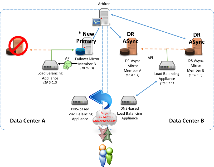
In a failover scenario to a different data center, (either a synchronous mirror or DR asynchronous mirror member in an alternate data center) using either the API or polling methods, the newly promoted primary mirror member starts reporting as primary to the local network appliance.
During the failover, the data center that was once contained the primary is now no longer reporting “Up” from the local load-balancer to the geographic/global. The geographic/global appliance will not direct traffic to that local appliance. The alternate data center’s local appliance will report “Up” to the geographic/global appliance and will invoke the DNS record update to now direct to the Virtual IP presented by the alternate data center’s local load-balancer.
Option-4: Multi-Tier and Geographically Dispersed Deployments
To take the solution a step further, the introduction of a separate web server tier is made either as an internal to private WAN or accessible via Internet. This option may be a typical deployment model for large enterprise applications.
The following example shows a sample configuration using multiple network appliances to securely isolate and support the web and database tiers. In this model two geographically dispersed locations are used with one location deemed the “primary” location and the other location is purely “disaster recovery” for the database tier. The database tier disaster recovery location is to be used in the event the primary location is out of service for any reason. Additionally, the web tier in this example will be illustrated as being active-active meaning users are directed to either location based on various rules such as lowest latency, lowest connections, IP address ranges, or other routing rules you deem appropriate.
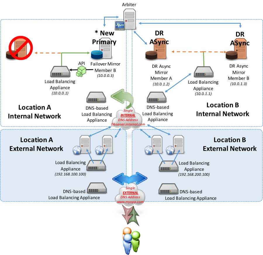
As the above example shows, in the event of a failover within the same location automatic failover occurs and the local network appliance now points to the new primary. Users still connect to either location’s web servers and web servers with the their associated CSP Gateway continue to point to Location A.
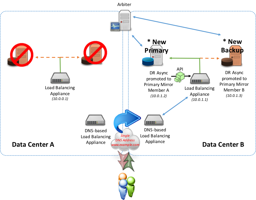
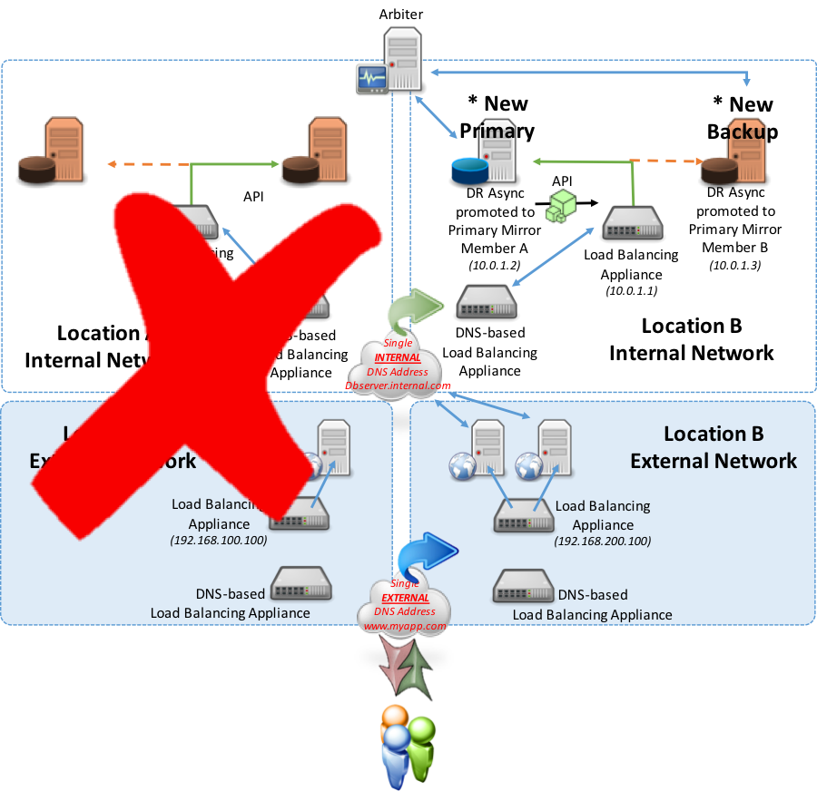
In the next example, consider an entire failover or outage at Location A in which both the primary and backup failover mirror members are out of commission. The DR Async mirror members would then be manually promoted to primary and backup failover mirror members. Upon that promotion, the new designated primary mirror member will allow Location B’s load balancing appliance to report “Up” using the API method discussed earlier (polling method is an option as well). As a result of the local load balancer now reporting “Up”, the DNS-Based appliance will recognize that and redirect traffic from Location A to now Location B for database server services.
Conclusion
There are many possible permutations of designing mirror failover without a Virtual IP. These options can be applied to either the simplest of high availability scenarios or multi-geographic region deployments with multiple tiers including both failover and DR Async mirror members for a highly available and disaster tolerant solution aiming to sustain the highest levels of operational resilience for your applications.
Hopefully this article has provided some insight on the different combinations and use cases possible for successfully deploying database mirroring with failover that are suitable for your application and availability requirements.